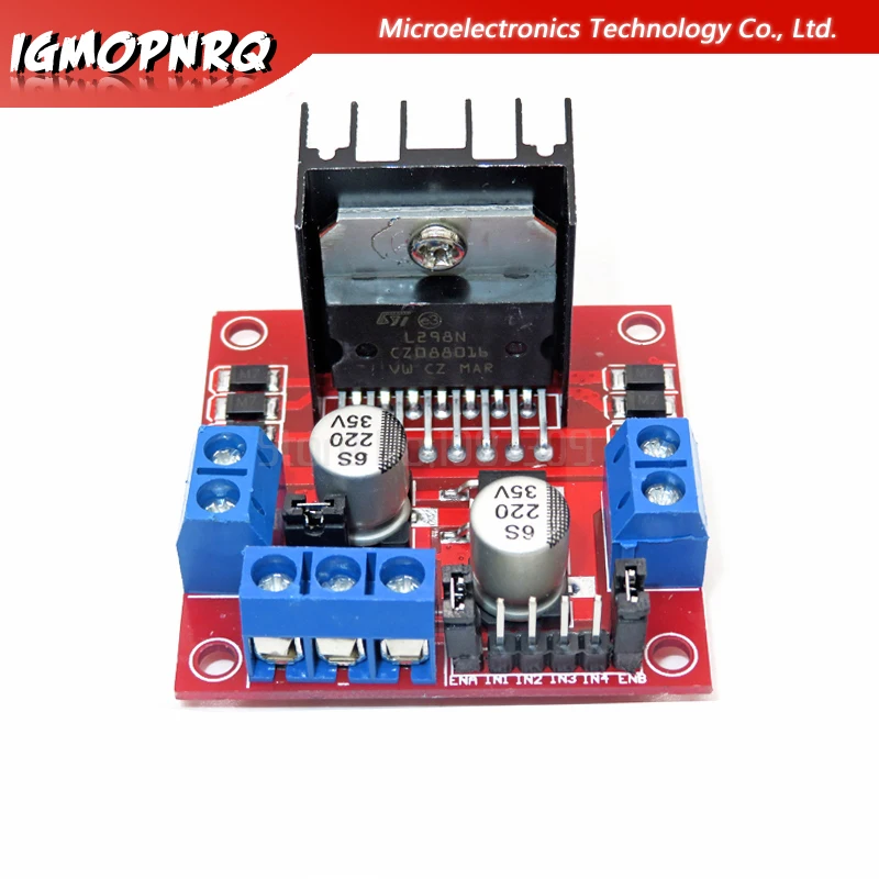

Remove jumper and connect to PWM pin on microcontroller if using speed control.
#L298N STEPPER MOTOR DRIVER CONTROLLER BOARD MODULE MANUAL FULL#
If using the module with DC motors they can be left on if it is always desired to run the motors at full speed.

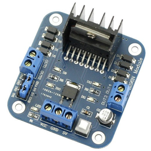
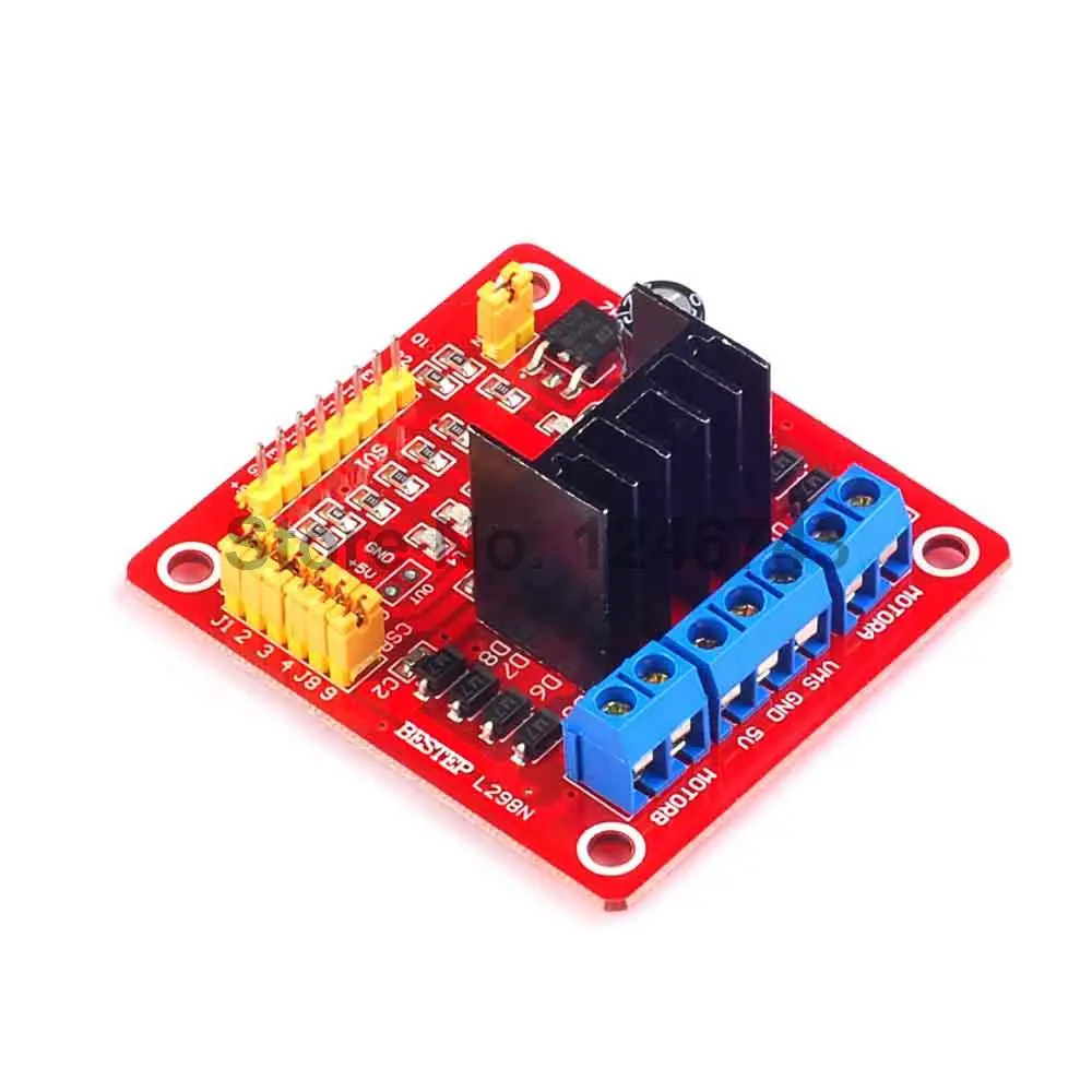
These jumpers are left on when using the module with a stepper motor. As shipped, these pins are jumpered to 5V (HIGH) which means they are constantly enabled. The ENA & ENB pins are the enable pins for the 2 H-Bridge motor controllers in the L298N and are active HIGH. NOTE: You cannot input voltages on both the Vcc and 5V terminals at the same time or damage may result. Using the Vcc input with a voltage between 7-12V gives the most flexibility when using this module and is the recommended mode to use. If Vcc is higher than 12VDC, it is not recommended to use the built-in 5V to power other devices to avoid possible overheating of the 5V regulator. The built-in 5V regulator can handle up to 400mA maximum. If the input voltage is in the range of 7 – 12VDC, there will be 5V available at the 5V terminal that can be used to power an Arduino or other 5V logic. The Vcc input feeds a built-in 5V regulator which is used by the L298N chip. If instead, you use the 5V power input, the switch is bypassed and the board will always be powered. When Vcc is enabled a red LED will light. There is a power button on the module that enables the Vcc input. The module can be powered either by inputting 7 to 35V on the Vcc terminal or by inputting 5V on the 5V terminal. The module has a Vcc input terminal and a 5V terminal which can either be an input or an output. Motors require a minimum amount of voltage to start turning, so low PWM values may not move the motors but you may be able to hear the motors humming. As the duty cycle is changed, the average DC voltage as seen by the motors also changes which changes the speed at which the motor turns. PWM stands for Pulse Width Modulation which means that the duty cycle (signal HIGH vs signal LOW) of the waveform can be changed. This gives full control over the DC motors. In addition PWM can be used to control the speed of the motors. When used with DC motors, the H-Bridge drive arrangement allows the direction of the rotation of the motors to be changed. L298N modules do not have built-in current limiting, so they are best suited for DC motor control rather than stepper control, so that is what we are going to focus on here. The module can handle up to 2.5A peak per bridge or 2A continuous and 25W total power. 2.5A peak current per channel (2A continuous).Drive 2 DC motors with speed and direction control.KEY FEATURES OF L298N DUAL H-BRIDGE MOTOR CONTROL MODULE: L298N Dual H-Bridge Motor Control Module.

The L298N Dual H-Bridge Motor Control Module can be used to control 2 DC motors or 1 stepper motor at 2A continuous current per channel.


 0 kommentar(er)
